Analog-to-Digital Converter
Overview
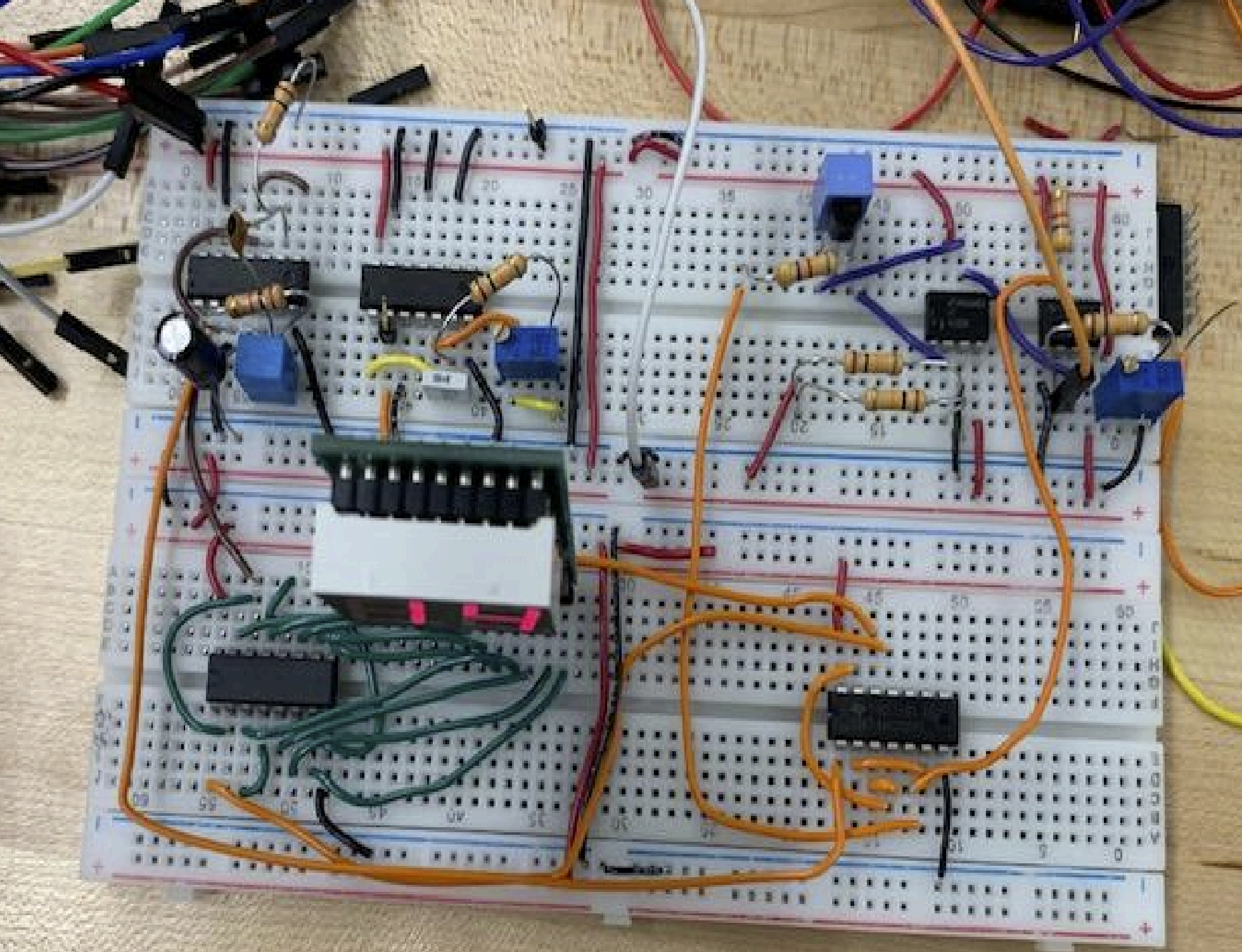
As the final project for ENPH 259, I constructed a fully functional Analog-to-Digital Converter (ADC) using fundamental electronic components. This ADC translates analog signals into digital values and displays the result on a 7-segment display, with each unit representing 0.1 volts.
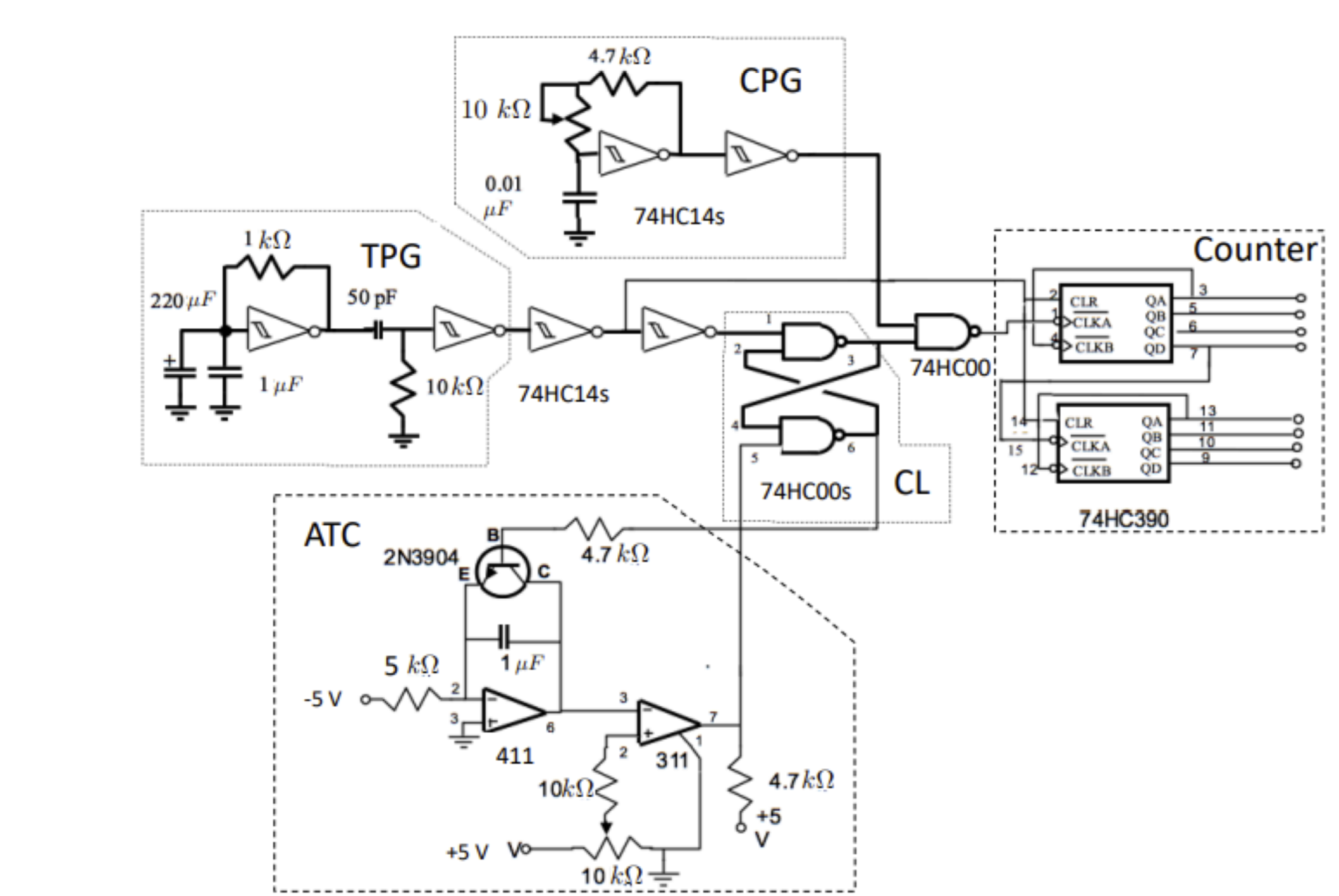
The overall project consists of the following subcomponents:
- Trigger Pulse Generator: Clears the counter and starts the time measurement.
- Clock Pulse Generator: Produces a square wave for timekeeping.
- Counter: Counts the clock pulses during the time window generated by the analog voltage.
- Analog-to-Time Converter (ATC): Converts analog voltage into a proportional time interval.
- Control Logic: Coordinates the ADC operations by controlling counting and reset signals.
Key Highlights:
- Calibrated the ADC to ensure accurate voltage-to-digital conversion within a functional range of 0-5V.
- Debugged and resolved critical issues like improper waveforms, incorrect counting, and voltage calibration errors.
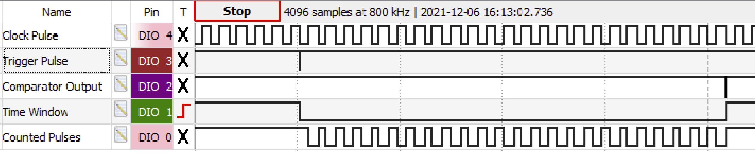
- Developed a timing diagram to verify and visualize the ADC’s operation.
Technologies and Tools
- Circuit Design Components: Schmitt triggers, NAND gates, operational amplifiers, flip-flops, 7-segment displays
- Instruments: Oscilloscope, digital multimeter, function generator, Analog Discovery 2
- Software: Waveforms
Gallery